
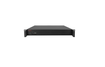
16+1+1 Port AI PoE Switch 7905
Instruction manual
《User Manual》mainly introduce 7905 hardware feature, installment method, and attention items.
Including these sections:
The first section of the product introduction. Mainly introduce POE switch function, feature, and appearance. The second section product installment. Guide POE switch hardware installment method and attention items. The third section hardware connection. Guide POE switch connection with other devices and attention items.
The fourth section: technical specification.
| Declare: In order to avoid device, is damaged and personal injury, please carefully read the user manual correlation content. |
Appointment
Part pictures are diagrammatic drawing, the picture can exist difference with the product. The icon reminds the attention items if the incorrect operation can cause the device is damaged
The first section Product Introduction
1.1Product Profile
7905 is AI POE switch, 16 10/100Mbps POE port with1Gigabit combo port. 7905 can carry power to IP camera, wireless AP, wireless bridge, IP phone. 7905 is with 4 working mode, In AI VLAN mode, 1 -16 ports are isolated from each other, which can effectively restrain network storms and improve network performance. In AI Extend mode, the effective transmission distance of 1-8 ports can reach 250 meters, which is suitable for remote monitoring and power supply. In the AI power supply mode, the switch automatically detects the working status of the PD device and finds that the device abnormal automatically restarts the device. In AI QOS mode: the video data will be processed preferentially when the device is congested to make the video smoother TV-AI6016 support IEEE802.3af/at, auto-identification power device, so don’t worry it will destroy the private standard POE or non-POE device.
1.2 Package content
Opening packing box, please carefully check the following content
| Content | Quantity | Declaration |
| POE switch | One piece | \ |
| Power cord | One piece | Supply power |
| Bracket | Two piece | Rack mounted |
| User manual | One piece | Install guide |
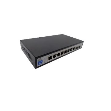
1.3 Product Appearance
- Front panel
Including indicator light, RJ45 port, DIP switch, SFP port, the picture is as follow:
Indicator light
7905 indicator light working information is as follow:
| LED | Name | Color | Working states | Declaration |
| POWER | Power LED | Red | ON | power normally |
| Off | Don’t have power、power switch doesn’t turn on, power abnormal | |||
| LINK/ACT (17) | Device connection LED | Green | blink | Corresponding already connect normally |
| Off | Corresponding port don’t connect normally |
- RJ45 Port
7905 support 16 port 10/100Mbps,IEEE802.3af, IEEE802.3at standard POE supply power. When working mode is Extend mode, port1-port 8 can support 250m supply power
7905 is with two 10/100/1000Mbps combo port, use 17, indicator light in common
- SFP Port
7905 is with one gigabit SFP port(SFP1), use for gigabit SFP module.
- Working mode key
AI Extend: 1-8 port supports 250M meters long distance power supply (recommended cat 5 or above)
AI VLAN:Isolating ports 1-16 from each other, restrain network storms effectively and improve network performance
AI QOS:Prioritize the identified video data to make video transmission smoother
AI PoE: Automatic detection power of port, power off and restart the device if find
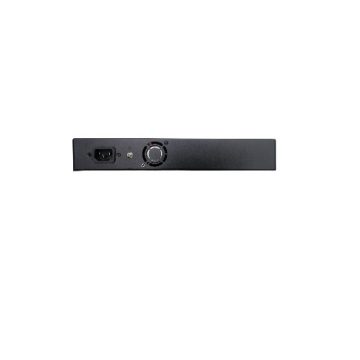
- Rear panel
Including:Power socket、power switch、ground terminal
- Power socket
The connection power cord to POE switch 7905 power supply is AC100-240V~50/60Hz.
- Ground terminal
Please use guideline ground connection, in case of lighting stroke. In order to avoid the product, sustain lighting stroke and extend using lifetime.
The second section product install
1.1 Install attention items
Attention:Avoid incorrect using caused device is damaged and personal injury, please carefully read the following of attention items
- The install safety attention items
- During install make sure power supply keep turn off states, put on anti-static wrist, guarantee the anti-static wrist have good touch with skin, avoiding the potential safety loophole;
- POE switch can work normally under the correct power supply, please confirm the supply power voltage corresponds with the marked voltage;
- Before POE switch supply power, please confirm it won’t cause power supply circuit overload, for fear that affecting POE switch work normally, even cause unnecessary destroy;
- Avoiding electric shock dangerous, please don’t open the casing when POE switch work, even if without power condition, don’t open the casing too;
- Before clean POE switch should pull out power plug, please don’t use wet cloth scrub, please don’t use liquid cleaning;
- Temperature Humidity
In order to ensure PoE switch long-term steady operation, extend using lifetime, please maintenance a certain temperature and humidity. too high or too low environment humidity easier to cause insulation material electric leakage, variant, even metal parts rusting, high temperature speeds up insulation material aging processing, seriously affect device use lifetime. The POE switch working temperature and storage temperature/ humidity is as follow:
| Environment Description | Temperature | relative humidity |
| Working environment | 0℃~40℃ | 10%~90% RH non condensing |
| Storage environment | -40℃~70℃ | 5%~90% RH non condensing |
Elevation
The product is with this icon just only use for the less than elevation 2000m area safety using.
- Dustproof
Dustfall over POE switch surface can cause electrostatic adsorption, make a metal connection point poor touch. Although the product makes a certain measure of anti-static when static electricity exceeds a certain strength, still destroy component parts of the PCB, in order to avoid static electricity, affect product work normally, please pay attention to the items as follow:
regularly clean dust, keep indoor air cleaning; ensure device ground good, guarantee static electricity transfer smoothly
- Electromagnetic interference
Electromagnetic interference can affect the device internal capacitance, inductance, in order to reduce electromagnetic interference factor, cause an adverse effect, please pay attention to the following of items:
Supply power system adopt necessary anti-power grid interference measure; PoE switch should be far away from high-frequency power, high current device, such as wireless launch pad; If necessary, please make electromagnetic shielding measure
- Lighting protection requirement
When lightning strikes, at the moment will have a strong current, the air on the discharge path will be instantly heated to 20000 Celsius degrees, in the moment high current enough to cause fatal damage to electronic equipment.
In order to reach a better lightning protection effect, please note the following:
Make sure the rack is in good touch with the ground; Make sure the power socket is in good touch with the ground;
Reasonable wiring to avoid internal lightning; Outdoor wiring, it is recommended to use signal lightning protector;
- Installation platform requirement
POE switch is installed in a rack or on another horizontal workbench,
Please note the following:
Make sure rack or workbench smooth and steady, secure, it can bear 5.5kg weight at least; Make sure the rack has a good cooling system, or keep indoor well-ventilated; Make sure the rack is well grounded, power socket and POE switch don’t exceed 1.5meter
- Installation tools ready
During installation, may be used screwdrivers, antistatic wrist strap, network cable, fiber tools, please the user self-prepare.
2.2 Product Installation
The 7905 is designed for 13-inch case support desktop mounting or rack-mountable via a bracket. The desktop mounting tries to ensure the switch can be placed horizontally. The installation needs to ensure that the switch is not squeezed to ensure good heat dissipation.
The specific installation steps for rack installation are as follows:
- check the rack grounding and stability;
- two pieces L type bracket differentiate install to the two sides of POE switch panel and fix with screw
- Put POE switch on the appropriate location of the rack, crutch by a bracket; using the L-shaped bracket to fix the two sides of the rack with a screw, make sure the POE switch is installed on the rack smooth and steady.
Attention:
The rack has well-grounded is the important guarantee of anti-static, anti-leakage, lightning protection, anti-interference, so make sure the rack ground wired is properly installed; The rack-mounted device generally from down to up, avoid overload installation; Don’t put heavy things on the POE switch, in case happen accident;
Make sure cooling and air ventilation
The third section hardware connection
3.1 Connection RJ45 port
Using Ethernet cable connect POE switch to the RJ45 port of the opposite end network device,port17, port 18 is uplink port, other is downlink port, default the POE switch’s downlink port already open POE power function, it can send power to IP camera, wireless AP, wireless bridge.
Attention:
When POE switch is connected to a workstation, server, router, or other Ethernet devices, the Ethernet cable length cannot more than 100meter; The Ethernet RJ45 port Auto-MDI/MDIX function default open, when adopting Cat.5 cable to connect Ethernet network, both standard Ethernet cable, and crossover Ethernet cable can be used;
Don’t use RJ45 port to connect telephone cable.
3.2 Connection SFP port
7905 SFPport just only supports the gigabit SFP module. Suggestion to use the standard SFP module.
The process of POE switch install SFP module is as follow:
- Hold the SFP module from the side, insert it smoothly along with the SFP port slot of POE switch, until the SFP module is close touch with POE switch;
- When connection, please confirm SFP module RX and Tx port, the side of fiber optic corresponding insert Rx and Tx port, make sure Tx and Rx port connection correctly, another side of fiber connect to another device;
- after powered,please check the corresponding indicator light status. If light is on, show the link already connect normally, light is off, show the link is blocked. Please check circuit, confirm the opposite end device already start using.
Attention:
- Do not over-bend the fiber, the radius of curvature should not be less than 10cm;
- Make sure the cleanliness of the fiber surface;
- Please do not look directly at the fiber optical connector, otherwise, it can cause eye damage.
3.3 Inspection Before powered
Please check if power socket supply power is corresponding the specification or not;
Please check if power supply, POE switch, rack already grounded correctly or not;
Please check if PoE switch normally connect with other network equipment or not;
3.4 Device initialization
After powered after turn on the power, the POE switch will automatically initialization.
The indicator light will appear the following of the situation; After powered, the power indicator light always keeps ON, the other indicator lights OFF. After around two-second, except power indicator light, the other indicator light ON around two seconds, then OFF; Each port indicator light indicates the connection status of each port, it shows the POE switch starts work normally.

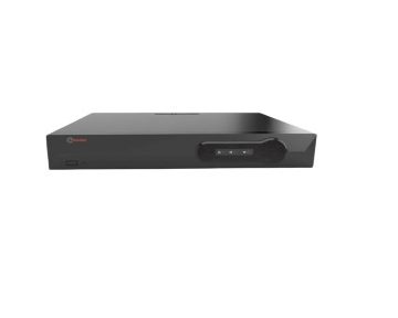
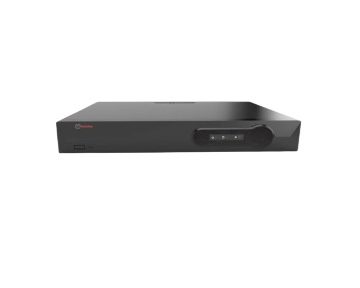
8+2 Port Gigabit Layer 2 AI PoE Switch 7910
The Product installation manual mainly describes 7910 PoE switch hardware features, installation methods, and precautions during the installation this manual includes the following chapters:
Chapter 1: Product Introduction. Briefly describes the basic features of the switch and the appearance details.
Chapter 2: Product Installation. Guide the switch hardware installation methods and precautions.
Chapter 3: Hardware Connections. Guide the connection between switches and other devices and precautions.
Chapter 4: Technical Specifications.
| NOTE: To avoid potential device damage and personal injury, read the related information in this manual before installing the device. |
Agreement
The term “switch” mentioned in this manual, unless otherwise specified, refers to 8-port full Gigabit managed PoE switch, hereinafter referred to as TV-AI2010GX Some pictures for the schematic, the product itself and pictures may be different
This icon indicates the items to be cautioned in the operation. If the operation is wrong, the equipment may be damaged and other adverse consequences.
Chapter 1 Product Introduction
1.1Product introduction
7910 is managed AI PoE switch for secure transmission and WIFI coverage, meet the WIFI AP, IP-camera, WIFI bridge, IP phones and other types of equipment PoE power supply needs. Products using a new generation of high-performance hardware and software platforms, providing flexible, cost-effective full Gigabit access and uplink ports, , complete security mechanisms, improved ACL / QoS strategy, and rich VLAN capabilities, it is easy to manage and maintain, meet the users’ requirements for network equipment easy to manage, high security and low cost. It is suitable for network access, aggregation and core applications in campus, hotel and enterprise campus.
PoE (Power over Ethernet) refers to the power over Ethernet technology. It refers to the transmission of data signals to some IP-based terminals (such as IP phones, the wireless access point AP, network cameras, etc.) and also provides DC power supply technology. These devices that accept DC power supply are called powered devices (PD)
1.2 Packing list
Open the package carefully check the following list
| Commodity | Quantity | Description |
| PoE switch | 1pcs | No |
| Power cord | 1pcs | Optional |
| Bracket | 2pcs | Fixed on rack mount |
| User manual | 1pcs | Guide users to install switch |
1.3Appearance
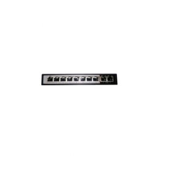
- Front Panel
Including indicators, RJ45 port, DIP switch, RST button, SFP port, CONSOLE port, as shown in
Figure 1.1 below
Indicators
7910 The indicator working status is shown as the following table
| Indicators | Title | Color | Work status | Description |
| POWER | Power indicator | Red | Solid | Power is normal |
| Off | No power, the power switch is not turned on, power supply is abnormal | |||
| POE | POE power indicator | Yellow | Solid | The corresponding RJ45 port is connected to the powered device and the power supply is normal |
| Off | The corresponding RJ45 port is not connected to the powered device or the power supply is abnormal | |||
| LINK/ACT | Connection indicator | Green | Blinking | A valid link is established |
| Off | An invalid link is established | |||
| SYS | System indicator | Green | Blinking | System is functioning properly |
| Off | System is functioning improperly Software is damaged | |||
| 9-10 | SFP indicator | Green | Blinking | A valid link is established on the SFP port |
| Off | An invalid link is established on the SFP port |
- Shortcut button
- Ai QOS: Improve video data processing capabilities and improve the monitoring of Caton and Mosaic phenomena in the network
- Ai Extend: 1-8 port rate down to 10Mbps, but the transmission distance up to 250 meters
- Ai VLAN: Isolating ports 1-8 from each other, suppress network storms effectively and improve network performance
- AI PoE Detect PD, power failure and restart dead equipment
- RJ45 Port
7910 with 8 10/100/1000Mbps PoE port, all ports support IEEE802.3af and IEEE802.3at standard When the switch mode of operation is CCTV mode, 1-8 port can support 250 meters power supply with 10Mbps speed rate
- SFP Port
AI2010GX provides 2 Gigabit SFP optical ports (SFP1, SFP2), can be inserted into the Gigabit SFP module
- RST Button
- When the switch is powered on, press the button with the needle to release the device and enter the restarting state. When the SYS lamp restarts, the device restarts. When the switch is powered on, press and hold the button for more than 5s to release the button and enter the reset state. When SYS is re-lit, the device is reset successfully
Chapter 2 Installation
2.1Installation Precautions
Note:To avoid improper use of equipment damage and personal injury, please observe the following precautions
- Installation safety precautions
- The power should be kept off during the installation, while wearing anti-static wrist, and to ensure well touch between anti-static wrist and skin to avoid potential safety hazard;
- The switch just works normally when it is powered by the correct power supply. Make sure that the power supply voltage matches the voltage indicated by the switch
- Before powering on the switch, make sure that the power circuit is not overloaded, which may affect the normal operation of the switch and even cause unnecessary damage
- To avoid the risk of electric shock, do not open the case while the switch is working. Do not open the case even when it is not powered
- Before cleaning the switch, unplug the switch from the power cord and do not wipe it with wet cloth. Do not wash it with liquid
- Temperature and humidity
To ensure the long-term stability working of the switch, please maintain a certain temperature and humidity environment. High or low humidity easily lead to leakage of insulation materials, deformation and even the corrosion of metal parts, the temperature is too high will accelerate the aging process of insulating materials, seriously affecting the service life of the equipment. The normal operation of this series of switches and storage temperature/humidity are as follows
| Environmental
description |
temperature | Relative humidity |
| Working environment | 0℃~40℃ | 10%~90% RH no condensation |
| Storage environment | -40℃~70℃ | 5%~90% RH no condensation |
- Altitude
Products with this logo are only for safe use in areas below 2000m altitude
- Dust-proof
Dust on the switch surface will cause electrostatic adsorption, poor contact of the metal contacts. Although the device itself has done some measures in anti-static, when the static electricity exceeds a certain intensity, it will still cause fatal damage to the electronic components on the internal circuit board. In order to prevent static electricity from affecting the normal operation of the equipment, please note the following:
Regular dust, keep the indoor air clean;
Make sure the equipment is well-grounded to ensure a smooth transfer of static electricity
- Electromagnetic interference
Electromagnetic interference have an impact on the device capacitance, inductance and other electronic components by capacitance, inductive coupling, impedance coupling and other conductive, in order to reduce the adverse effects caused by electromagnetic interference, please note the following:
Power supply system to take the necessary anti-grid interference measures; Switches should be far away from high-frequency high-power, high-current devices, such as wireless transmitters; If necessary, take electromagnetic shielding measures
- Lightning protection
When a lightning strike occurs, a strong current will be generated in an instant cause fatal damage to electronic equipment. To achieve better lightning protection, please note the following:
Make sure the rack and the ground to maintain good contact; Make sure the power outlet is in good contact with the earth; Reasonable wiring, to avoid the internal sense ray; Outdoor wiring, it is recommended to use the signal lightning protection device
- Installation desk requirement
Regardless of whether the switch is installed in a rack or on another horizontal workbench, be aware of the following: Make sure the rack or workbench is stable, strong, and can withstand at least 5.5Kg weight; Make sure the rack has a good cooling system, or maintain good indoor ventilation; Make sure the rack is well grounded, the power outlet and switch are within 1.5 meters
- Prepare tools for installation
You may need to use a screwdriver during installation, electrostatic wrist strap, fiber optic cable and other tools to prepare your own
Chapter3 Hardware connection
3.1RJ45 port connection
Connect the RJ45 port of the switch and the corresponding network device via cables, the POE power supply function of the switch is default enabled on the downlink port of the switch, which can be used for IEEE802.3af or IEEE802.3at standards powered devices such as APs, bridges, and network cameras
Note:
When the switch connected workstations, servers, routers or other ethernet devices the cable length should be within 100 meters; The Auto-MDI / MDIX ethernet interface is enabled by default. Category 5, the standard network cable or crossover cable can be used for Ethernet connection.
Do not connect the RJ45 port to the phone line
3.2 SFP Port connection
7910 SFP port only support Gigabit fiber module. Recommended use of standard SFP module products The process of installing a fiber module on a switch is as follows:
First, grasp the optic fiber module from the side, insert it smoothly along the SFP port slot until the optic fiber module and switch are in close contact;
Second, confirm the Rx and Tx ports of the fiber module when connecting, insert one end of the fiber into the Rx and Tx ports correspondingly, ensure that the Tx and Rx ends of the interface are connected correctly and the other end of the fiber is connected to another device;
Third, please check the corresponding indicator light status after power on. If the light blinking that the link is properly connected, if the light is off, the link is a failure, please check the line to confirm that the corresponding equipment is enabled.
Note:
Does not allow excessive bending fiber, the radius of curvature should not be less than 10cm; Ensure the cleanliness of the fiber surface; Please do not look directly into the optical fiber connector with your eyes as this may cause eye injury
3.3 Check before power on
Check whether the outlet power supply meets the switch specifications; Check the power, switches, racks and other equipment have been properly grounded; Check whether the switch and other network devices are connected properly
3.4 Device initialization
The switch automatically initializes when the power switch is turned on. The indicator will appear in the following situation:
After the power is turned on, the power indicator remains on, the other indicator is off at this time; After about 1 second, all lights except for the power light turn on for about 35 seconds and then turn off; when the SYS light goes flashing, the system runs normally Port LEDs indicates the connection status of each port, indicating that the switch has started to work normally
3.5 Web Login
Step1、In the normal operation of the device, connect the computer to the switch’s RJ45 port by network cables
Step 2、 Manually changed the computer IP address to 192.168.254.X (X is 2 ~ 254), subnet mask is 255.255.255.0
Step3、Open computer’s browser, type 192.168.254.1 in the address box, hit the Enter key
Step4、Enter the default username and password “admin” and then click Login
Step5、Entered the switch web management interface successfully when you see the picture as below, you can begin to configure the switch
8+2 Port AI POE Switch with 2GE Uplink 7904
7904is a Gigabit uplink 8-port 100M POE switch, it has three working modes, it has 4 working modes, AI VLAN mode, AI Extend video monitoring mode, AI PoE mode, AI QOS mode. All ports are free to communicate by default; In AI VLAN mode, 1 -8ports are isolated from each other, which can effectively restrain network storms and improve network performance. In AI Extend mode, the effective transmission distance of 1-8 ports can reach 250 meters, which is suitable for remote monitoring and power supply. In the AI power supply mode, the switch automatically detects the working status of the PD device and finds that the device abnormal automatically restarts the device. In AI QOS mode: the video data will be processed preferentially when the device is congested to make the video smootherTV-AI2082Gsupports the standard IEEE 802.3af/at protocol, which can automatically detect and identify the PD devices and supply power, therefore, Don’t worry about PoE or non-PoE devices that can damage private standards.
Key Features:
- AI Extend: 1-8 port supports 250M meters long distance power supply (recommended cat 5 or above)
- AI VLAN: Isolating ports 1-8 from each other, restrain network storms effectively and improve network performance
- AI QOS: Prioritize the identified video data to make video transmission smoother
- AI PoE: Automatic detection power of port, power off and restart the device if find a dead machine
- Support standard IEEE 802.3af/at protocol, automatically detect and identify the PD devices comply with IEEE 802.3af/at protocol and supply power.
- Support upward port auto MDI/MDIX.
- Adopted storage forward switching system.
- Smart power and minimum consumption, guarantee PD requirements.
- power supply circuit protection function and protection back-end device safety
- Automatically provide the adaptive device
- The finless design realizes saving energy and environment protection
- Compact size design
- Support saving power function when porting dis-connection
- All Ports support Wire-speed forwarding capability
- Plug and play, easy using without configuration.

4+2 Port Gigabit AI POE Switch 7906
7906 is 6 port built-in power 10/100Mbps PoE switch with 4 working modes, AI VLAN、AI Extend、AI PoE,and AI QOS. In Standard mode, all ports are free to communicate; In VLAN mode is enabled, 1-4 ports are isolated from each other, which can effectively suppress network storms and improve network performance. In the CCTV Extend mode 1-4 ports can effectively transmit distances up to 250 meters, which is suitable for remote monitoring and power supply. In the AI PoE mode, the switch automatically detects the working status of the PD device and finds that the abnormal device automatically restarts the device. In the AI QOS mode, when the device is congested, the video data is processed preferentially to make the video smoother. The device supports the standard IEEE 802 af/at protocol, which can automatically detect and identify the PDs that comply with the IEEE 802 af/at standard and provide power for them, so there is no need to worry about PoE or non-PoE devices that can damage private standards.
Main characteristics
- CCTV Extend: 1-4 ports support 250 meters long distance power supply (should be used cat5e or cat6 cable)
- VLAN: Isolating ports 1-4 to each other can effectively suppress network storms and improve network performance.
- AI QoS: Prioritize the identified video data to make the video transmission smoother
- AI PoE: Automatically detects the power receiving port, finds the dead device, and restarts the device after power off.
- Support wireless access points (APs) and network surveillance cameras via Cat 5 cables
- Support IEEE802.3af/at standard PD device
- Supports uplink port auto-flip (Auto MDI/MDIX)
- Adopt the store-and-forward exchange mechanism
- With power circuit protection, it can protect the security of the back-end equipment
- Zero configuration feature power is automatically supplied to the adaptive device
- No fan design to achieve energy saving and environmental protection
- Support port no link power saving function
HDD EXPANSION SHELF T34921
Features –
- Embedded design, stable, reliable and safe
- Meets the requirement of large scale surveillance system video storage
- 1 E-SATA interface
- Supports up to 9 SATA/SATAII HDDs
- Shockproof design
128 Channel 4K H.265 NVR – Pro Series H.265/H.264 T37447
Features –
- Support for H. 265/H.264 encoding format streaming access and decoding output.
- No need intelligent analysis support of IPC, NVR support local 8ch intelligent analysis: Target Count, Object Left/Lost, Area Detection, Line Crossing,
- Support ONVIF protocol, support High profile S, High profile G, compatible with different IP camera that based on ONVIF, RTSP standard.
- Adopt HDD sequence writing method and the data is written from 0 track which increase 2.5X lifetime of the HDD.
- Standard resolution which can be adjusted according to the display device in order to get the best image quality.
- The recording playback is shown by time bar and different colour represents different recording type. It is very fast and easy to find check the recording.
- The mouse roller can realize 15X digital zooming which the enlarged image can be dragged and moved randomly Under preview and playback modes.
- Immediate snapshot and immediate view; the picture will be stored in an independent area in the HDD
- Support IPC centralized management, including IPC parameter configuration, information import/output, two-way audio, upgrade, etc.
- Support motion detection data filler when do playback. support video summary playback.
- 2 HDMI Port & 2 VGA Port Output & Second HDMI port works as the auxiliary output
- Support instant playback for screen preview during multi-channel display mode.
- 16 SATA interfaces supporting hot-plug + 2 E-SATAT
- Flip-open chasis, prepositive slot type HDD installation , reliable and easy-maintainable Technical.
- Support HDD hot swap with RAID0,1,5,6,10 storage scheme configurable.
64 Channel 4K H.265 NVR – Pro Series H.265/H.264 T37389
Features –
- Support for H. 265/H.264 encoding format streaming access and decoding output.
- No need intelligent analysis support of IPC, NVR support local 8ch intelligent analysis: Target Count, Object Left/Lost, Area Detection, Line Crossing,
- Support ONVIF protocol, support High profile S, High profile G, compatible with different IP camera that based on ONVIF, RTSP standard.
- Adopt HDD sequence writing method and the data is written from 0 track which increase 2.5X lifetime of the HDD.
- Standard resolution which can be adjusted according to the display device in order to get the best image quality.
- The recording playback is shown by time bar and different colour represents different recording type. It is very fast and easy to find check the recording.
- The mouse roller can realize 15X digital zooming which the enlarged image can be dragged and moved randomly Under preview and playback modes.
- Immediate snapshot and immediate view; the picture will be stored in an independent area in the HDD
- Support IPC centralized management, including IPC parameter configuration, information import/output, two-way audio, upgrade, etc.
- Support motion detection data filler when do playback. support video summary playback.
- Support smart search, playback and backup
- Support instant playback for screen preview during multi-channel display mode.
- 9 SATA + 1 E-SATAT
- Support HDD RAID0,1,5,6,10 storage scheme configurable.
36 CH NVR 2HDD Support Upto 5MP T37935
• 36Ch NVR Support up to 5MP
• Support onvif , compatible with the camera
from other brands
• Max 6TB hardisk each SATA
• Compression: H.264/H.264+/H.265/H.265+
• Mobile Software: Truecloud
25 CH NVR 2HDD Support Upto 5MP T37555
• 25Ch NVR Support up to 5MP
• HDMI &VGA 1080P output
• Support onvif ,compatible with
camera from other brands
• Max 6TB hardisk each sata
• Compression: H.264/H.264+/H.265/H.265+
• Mobile Software: Truecloud

Network PTZ Keyboard Controller T17748
• H.265 compression
• ONVIF2.4 compatible
• 5’’ colorful LED display
• Support USB and HDMI output
• Easy to enable the function of IP PTZ
• 3D joystick, Plug and Play

IP PTZ 5MP 11 Array LED Array T17819
• IP PTZ 5 Megapixel • Support P2P viewing • 11pcs Array 42Mil Led+4PCS Laser LED, IR range up to 240M • ONVIF2.4 ; Compatible with HIKVISION, DAHUA, XM, CP Plus etc • Compatible with CMS, UC2, Milestone & AXXON platform etc • Intelligent IR illumination & power consumption is variable
IP PTZ 2MP 12 Array LED Array T17747
• IP PTZ 2 Megapixel
• Support P2P viewing
• 12pcs Array + 4PCS Laser Led,IR range up to 250M
• ONVIF2.4 ; Compatible with HIKVISION, DAHUA, XM,
CP Plus etc
• Compatible with CMS,UC2, Milestone & AXXON
platform etc
• Intelligent IR illumination & power consumption is
variable
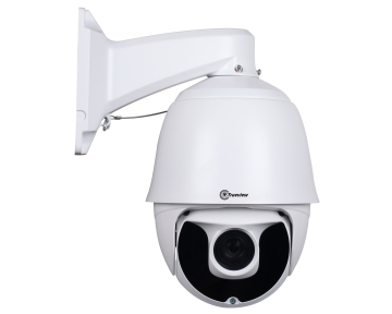
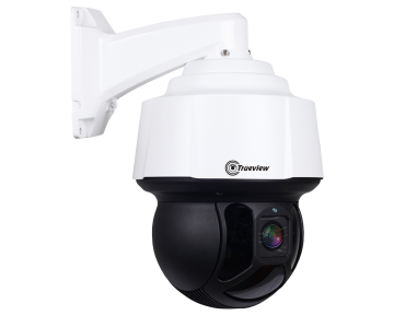
HD Starlight Speed Dome IP PTZ T17738
• Starlight IP Dome PTZ 2.0 Megapixel • Chipset: Sony185+Hi3516A • Lens: F=4.8MM -96MM • 36X optical zoom • Protocol: ONVIF2.4 • LED: 11 Array LED • 7″ Total Metal body construction, IP66 rate protection • Support P2P function
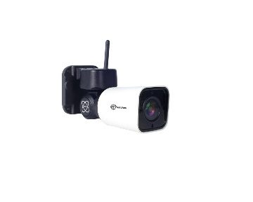
2MP HD Bullet Wireless IP PTZ T17799
• Support Micro SD Card 128G • Built-in Speaker and Micro Phone • Wireless Range: 100M (Depend on Environment) • Wireless Protocols: 802.11b/g/n • Software Control: IE, CMS, Mobile, App Android/Iphone • Support H.265/MJPEG Compression • Mobile Application: Truecloud
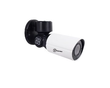
2MP HD Bullet IP PTZ 6 Array LED T17741
• Support ONVIF 2.4, P2P Function • IR range reach up to 50 Meters • Pan/Tilt/Zoom ,A-B scan, tour available • Support H.265/MJPEG Compression, Triple Stream, Video Output • Compatible with HIK/DAHUA/Milestone/ AEVISION/UC2 and AXXON platform
2MP Vandal Proof PTZ Dome 4 Array LED T17740
• 1.5 inch Vandal proof body,IP67.IK10 • IR range reaches up to 45 Meters • Pan/Tilt/Zoom, A-B scan, tour available • Support Onvif, P2P function • Support Audio, POE for Optional • Support H.265/MJPEG Compression, Triple Stream, Video Output • Compatible with HIK/DAHUA/Milestone/ AEVISION/UC2 and AXXON platform

IP POE IR Bullet Verifocal 5 MP 42 LED T17760
• Smart analysis: Target Count, Object Left /Lost, Area Detection, Line Crossing • ICR infrared filter for automatic switching from Day to Night mode and vice versa • Supports automatic electronic shutter function to adapt to different monitoring environments • High-performance 3D digital noise reduction & edge enhancement, using ROI video compression technology • Support …

PRO IP IR Bullet 5MP 48V POE T17829
• Smart analysis: Target Count, Object Left /Lost, Area Detection, Line Crossing • ICR infrared filter for automatic switching from Day to Night mode and vice versa • Supports automatic electronic shutter function to adapt to different monitoring environments • High-performance 3D digital noise reduction & edge enhancement, using ROI video compression technology • Support …
PRO IP IR Bullet 5MP 42 IR LED T17828
• Smart analysis: Target Count, Object Left /Lost, Area Detection, Line Crossing • ICR infrared filter for automatic switching from Day to Night mode and vice versa • Supports automatic electronic shutter function to adapt to different monitoring environments • High-performance 3D digital noise reduction & edge enhancement, using ROI video compression technology • Support …
PRO IP IR Bullet 5MP 42 IR LED T17692
• Smart analysis: Target Count, Object Left /Lost, Area Detection, Line Crossing • ICR infrared filter for automatic switching from Day to Night mode and vice versa • Supports automatic electronic shutter function to adapt to different monitoring environments • High-performance 3D digital noise reduction & edge enhancement, using ROI video compression technology • Support …

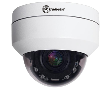
5MP PRO IP IR Dome T17700
• Smart analysis: Target Count, Object Left /Lost,
Area Detection, Line Crossing
• ICR infrared filter for automatic switching from
Day to Night mode and vice versa
• Supports automatic electronic shutter function to
adapt to different monitoring environments
• High-performance 3D digital noise reduction & edge
enhancement, using ROI video compression technology
• Support TRUECLOUD PRO APP P2P for mobile phone
or computer monitoring
• Power Input : PoE 48V/ DC 12V
• Compression: H.265
IP POE IR Bullet Varifocal 3MP 42 LED T17967
• IR Bullet Verifocal 3MP • ARM926 HI3516EV200 • 3.6MM Lens • 42 IR LED • Distance: 40-50 Meters • Power Input : POE 48V Standard/ DC 12V 1Amp • Compression: H.264/H.265/H.264+/H.265+
3MP PRO IP IR Bullet PoE 42 LED T17966
• Smart analysis: Target Count, Object Left /Lost, Area Detection, Line Crossing • ICR infrared filter for automatic switching from Day to Night mode and vice versa • Supports automatic electronic shutter function to adapt to different monitoring environments • High-performance 3D digital noise reduction & edge enhancement, using ROI video compression technology • Support …
3MP PRO IP IR Bullet PoE 42 LED T17965
• Smart analysis: Target Count, Object Left /Lost, Area Detection, Line Crossing • ICR infrared filter for automatic switching from Day to Night mode and vice versa • Supports automatic electronic shutter function to adapt to different monitoring environments • High-performance 3D digital noise reduction & edge enhancement, using ROI video compression technology • Support …
3MP PRO IP IR Dome T17962
• Smart analysis: Target Count, Object Left /Lost, Area Detection, Line Crossing • ICR infrared filter for automatic switching from Day to Night mode and vice versa • Supports automatic electronic shutter function to adapt to different monitoring environments • High-performance 3D digital noise reduction & edge enhancement, using ROI video compression technology • Support …
3MP PRO IP IR Bullet 18 SMD LED T17961
• Smart analysis: Target Count, Object Left /Lost, Area Detection, Line Crossing • ICR infrared filter for automatic switching from Day to Night mode and vice versa • Supports automatic electronic shutter function to adapt to different monitoring environments • High-performance 3D digital noise reduction & edge enhancement, using ROI video compression technology • Support …
3MP PRO IP IR Dome 6 Array LED T17960
• Smart analysis: Target Count, Object Left /Lost, Area Detection, Line Crossing • ICR infrared filter for automatic switching from Day to Night mode and vice versa • Supports automatic electronic shutter function to adapt to different monitoring environments • High-performance 3D digital noise reduction & edge enhancement, using ROI video compression technology • Support …
2.0MP H.265+ Bullet IP T17556
• IR Bullet 2.0 HD Megapixel • ARM9 RTOS HI3516E • Lens: 3.6MM • 4 Array LED (2 white LEDs and 2 IR LEDs) • Distance: 30 Meters • Power Input : DC 12V/1A • 2.4 Onvif version • Compression: H.264/H.265/H.264+/H.265+
Starlight PRO IP IR Bullet 2MP T17704
• Smart analysis: Target Count, Object Left /Lost,
Area Detection, Line Crossing
• ICR infrared filter for automatic switching from
Day to Night mode and vice versa
• Supports automatic electronic shutter function to
adapt to different monitoring environments
• High-performance 3D digital noise reduction & edge
enhancement, using ROI video compression technology
• Support TRUECLOUD PRO APP P2P for mobile phone
or computer monitoring
• Power Input : POE 48V Standard/ DC 12V
• Compression: H.265
Starlight PRO IP IR DOME 2MP T17703(T17703)
• Smart analysis: Target Count, Object Left /Lost, Area Detection, Line Crossing • ICR infrared filter for automatic switching from Day to Night mode and vice versa • Supports automatic electronic shutter function to adapt to different monitoring environments • High-performance 3D digital noise reduction & edge enhancement, using ROI video compression technology • Support …
